Foundations for Ground Mounted Systems
There are a number of ways that a ground mounted PV system can be anchored to the ground. This will focus on methods that are practical for DIY projects, and will gloss over methods that require heavy equipment or highly specialized machinery. Both fixed mounts and trackers can use the same principles, only for a tracker, the scale of the anchoring system is much larger.
The mounting system has not only to withstand the downward forces due to snow loading, but in addition forces in all directions due to high winds. The wind forces can at times produce a large upward force, so the anchoring to the ground must be able to resist forces in all directions.
The first consideration is to understand the type of ground that you have. If you have stable soil with no rock with a depth exceeding the frost line and at least 5' deep then you have the most options available to you. A Civil Engineer will be able to determine if your soil has sufficient holding power for some of the larger mounting systems.
If you have soil with variable depth to bedrock, then you can use an anchoring system that does not require an exact spacing between mounting points, and still use the soil to hold your panels in place against the forces of the wind. This is provided you can find places where you can get down below the frost line, these may not be conveniently located on a grid.
If you have very shallow depth to rock, then the soil can't be expected to resist all of the forces, and so if the rock below is solid bedrock you can anchor directly to the rock. However if the rock is shale or otherwise has poor holding power, then you will be forced to use a ballasted approach, the same as if there was no soil depth at all. The term ballasted means that weight alone of some heavy material keeps the structure in place.
The last class is where there is only a shallow depth of soil and then you encounter solid rock. The only choices are to anchor the mount to the rock, or to use a ballasted mount.
All of the above can be distilled into a smaller number of foundation solutions, which are:
- Holes sunk below the frost level and filled with concrete, possibly using Sonotubes
- Use Earth Screws, a pipe with a helical thread on the bottom augered into the soil to below the frost level and deep enough to resist uplift forces from the wind.
- Use a ballasted mounting system that floats on the ground surface.
- Anchor directly to rock using expanding bolt anchors, and a flat flange on the bottom of a pipe or if a distributed frame, to directly hold the frame in place.
- Have a hole(s) drilled in the rock by a well driller, or Pole Line contractor and anchor the pole(s) in place with concrete.
Types of mounts to be anchored.
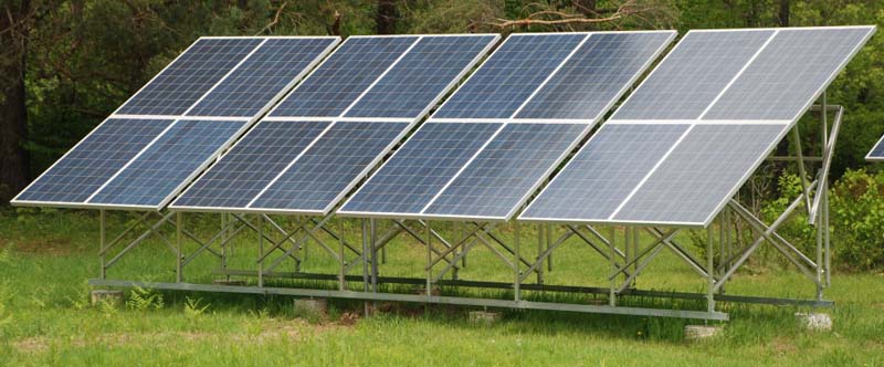
A distributed frame is one where a group of panels is supported by four or more piers or posts. The example in this photograph is a standard product that can be supplied as a kit. Note that this specific product has a seasonal tilt angle adjustment. It can be locked into two different angles, and does not require tools to make the change.
A DIY distributed frame mount's foundation could be could be constructed with pipe or poles embedded in the concrete which also provide some of the above ground structure, or bolted to the top of a pier. This type of mount is most easily made from scratch by the DIY person, either with pressure treated wood or from metal if you are proficient with welding. This requires a number of moderate sized concrete piers. There is no heavy equipment required, and assembly requires only common hand tools.
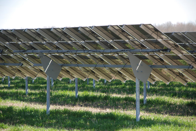
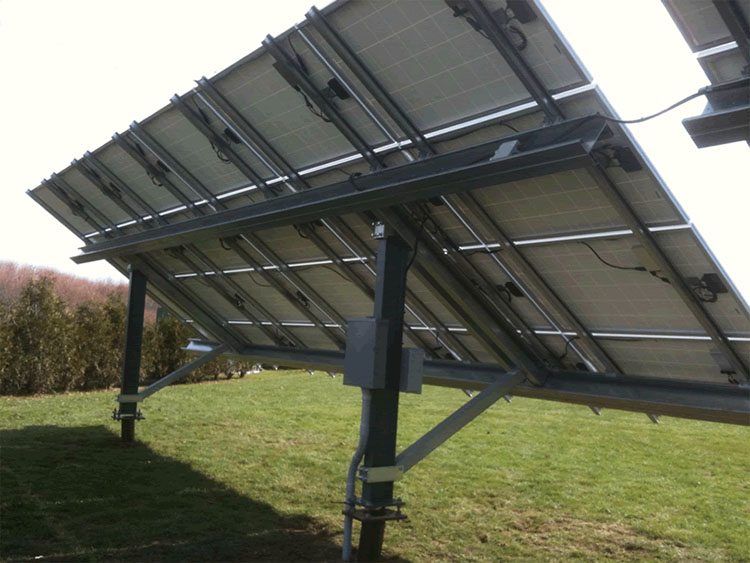
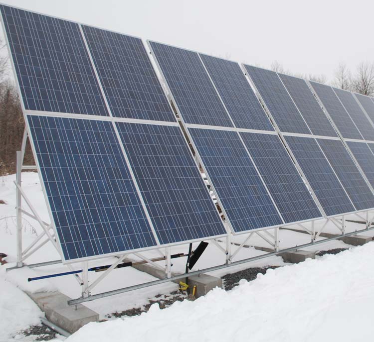
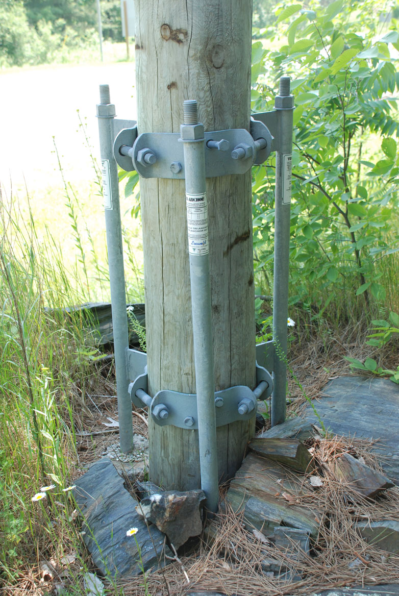
The image at the top of the page shows a two pole "top of pole mounted" frame. This requires two larger poles, or as in this case, Earth Screws. On another page you can watch a video of the Earth Screws being inserted for this project. Unirac's ISYS is one of many companies that has an Ontario qualified system of this type. The Unirac product and many others require two poles for every 5kW of panels. The picture at the top is at a solar farm, and the brand of mount is unknown. The photo below is of the Unirac ISYS system, which uses steel I beams for maximum strength.
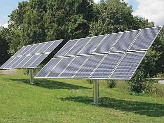
The last type is a single pole "top of pole mounted" frame, such as made by by True North Power. With the PS-2000C the mounting supports ten 230W panels per pole, and so five poles are required for a 10kW installation. Due to the smaller scale pole required, this is a reasonably easy product to install without any heavy equipment. It is also easier to install on a sloped site.
There are a variety of ballasted mounting systems available. These can be installed without any specialized tools and can work well of a level site. The one disadvantage of a ballasted system at ground level is the soiling of the panels due to rain splash, and there is nowhere for snow to slide off in the winter. On a flat roof this would be called a "non-penetrating" system, as no bolts would pierce the built-up surface of a flat roof, and so they are quick to install and do not have any risk of causing a leak. A sloped metal frame is assembled and after the panels are attached, there are trays where prefabricated cement blocks are inserted to weigh the mount down, or sandbags or other local heavy granular fill is inserted. Usually these mount one panel high in portrait orientation.
Here is an example of a ballasted ground mounted distributed frame made by True North, the PS-2400G. This uses four instances of 220 kg precast ballast blocks. Presumably the ballast could be cast in place to save on shipping. The panels are higher above the ground, and so rain splash is not a problem, and there is more space for snow to fall off the panels and not build up to the extent that it starts to block light falling on part of the panels.
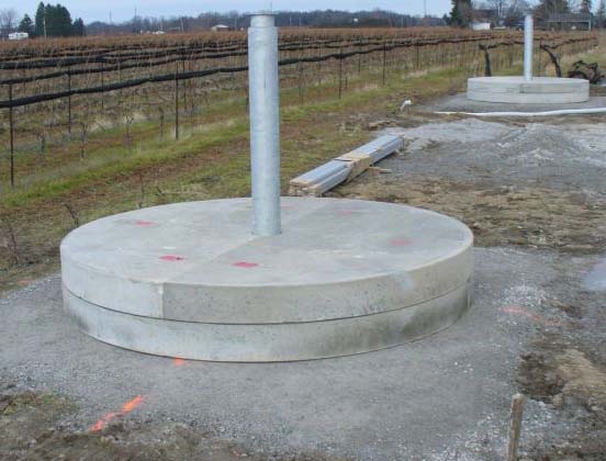
Concrete Piers
The first method is similar to what is done for fence posts, a circular hole in the ground is oversized enough that a pipe can be placed in the center of the hole, and a suitable amount of concrete fills the hole and anchors it in place. This is usually done with Sonotubes. When the pipe supports a "top of pole" panel mounting hardware , with only one pole per set of panels, then additional precaution is taken to make certain that the pipe can't rotate inside the concrete pier. Either weld a couple of pieces of rebar to the bottom foot of the pipe or drill a hole through the side of the pipe in a horizontal direction, and put a tight fitting bolt and nut through the hole. About 3/4 inch to 1" hot dipped galvanized nut and bolt would be suitable. For all other cases of more than one pole per set of mounting hardware, this precaution is not required. Multiple poles can be used to support a distributed frame.
The benefit of using Sonotubes is that you use less concrete, and the sides of the concrete cylinder that you pour are smooth, and has less surface area. The smooth surface is less likely to be subject to adfreeze and so uplift forces due to frost heave action on the sides of the cylinder is less likely move your pole or pier.
When no pole is required above ground, use either Sonotubes, or tapered forms such as made by foottube which are more resistant to frost action. The concrete pier protrudes a few inches above the average grade level. Reinforce the cylinder with rebar to increase strength against wind induced uplift forces and use a hot dipped galvanized post saddle or post mount if the above ground mounting is made of pressure treated wood, or a suitable hot dipped galvanized J bolt as used for house foundations sill plate anchoring if a metal frame it to be attached to the top of the concrete cylinders. If using a distributed frame, then a product called Unistrut may be useful if the location of the anchor points is not ideal due to avoiding rocks. This is used in exactly this way in the photograph used to illustrate the distributed frame.
Earth Screws For Anchoring Poles
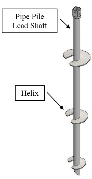 This is a convenient way to anchor poles into the ground when a suitable type of soil exists. There is no concrete used, and after the lifetime of the project is completed, these are easily removed compared to concrete piers. A Bobcat with a suitable attachment is commonly used to insert these devices, and all that are required can be inserted in a few hours. It also provides the most minimal disturbance to the site. A fence post contractor would install these for you, and provide access to a Structural Engineer that can specify the correct type and size of Earth Screw for your application and soil conditions.
In high wind conditions, helical piers can also provide protection against uplift. When the highest helix has reached a depth at least five times its diameter into suitable soils, the uplift capacity is approximately equal to the compression capacity.
A benefit for commercial installers is that as soon as the piles are installed in the ground, the rest of the installation con proceed, there is no waiting for concrete to cure.
For shorter lengths and lighter loads fewer helixes are used, and often only one at the bottom is used for solar applications.
On the mount types page you can watch a video of the earth screws being inserted for the project shown in the top photograph.
Ballasted Foundation
Many types of distributed mounting systems could be anchored to precast curbs, which look similar to railroad ties, and usually have two holes to use for mounting purposes. A typical example made by Lafarge weights about 400 lbs each. When these are used together with the Unistrut rails, a convenient mounting base is created for bolting on a distributed frame such as the one shown below.
This is the same type distributed mounting system shown earlier, in the winter position, and again the Unistrut rail is used to link them together and to make the curb placement non-critical. This requires little site preparation. The site is levelled, a layer of gravel is put in place for drainage and the curbs positioned on top. As stated earlier, the curbs could also be formed and poured in place, but this is a slower procedure. Some installations use a continuous curb that runs at 90 degrees to that shown in the picture above.
The important issue for the DIY solar project is finding a source of precast curbs near your location, to keep the cost of transportation reasonable. If there is no supplier nearby, then you could make your own re-usable form, and cast one a day using bags of premixed concrete, and a little wire mesh for reinforcement. To create bolt holes you could put in two bolts with a plastic tube over it to prevent the concrete sticking to the bolt, and use some concrete release compound. Use a release compound each time, and assemble the forms with bolts so that it can be taken apart to release the casting without damaging the form. Since each bag makes about 75lbs of concrete, you need a form to hold 5 bags to make a curb of about 375 lbs, and this will cost about $20 for material. Make sure you have machinery to move the curb after you have cast it, or if not, cast it in place. If you cast it in place, then use a hot dipped galvanized J bolt for your anchors. Make a jig so that they go in the same place in each curb.
There are also pole mounted systems with a prefabricated ballasted base that anchors the pole in place. The downside of this is that machinery is needed to lift the base, and the shipping costs of the base could be substantial. True North Power makes such a pole mount, but my distributor does not carry this product. Look at the True North SP-3600 for an example of a one piece prefabricated base that weights 20,000 lbs and comes in four segments. This appeals to large installation companies that have suitable heavy equipment since they can install that base and assemble the tracker in one day. This is not practical for a DIY person unless you live beside a precast company that can make these for you, and put them into place.
Here is a different approach to a precast base. This is a 10 ton one piece precast base with the mounting column for a Deger 5000HD tracker that was shipped as one unit, and unloaded onto a 2' bed of crushed stone.
The installation crew took about 4 hours to unload two of these precast bases, and to use the same delivery truck's crane to lift the metal frame complete with panels that had been previously attached up and mount the assembly on the column. This delivery was done in the winter, illustrating another benefit of using a precast system. This installation is done with the top of the gravel about 1' above the grade. There is no reason that this same system could have excavated the soil and have the crushed stone layer below ground to achieve any desired amount of height above the finished grade, including a flush result, providing that there is sufficient soil depth before encountering rock.
Anchor Directly to Rock
When there is little to no soil depth above solid rock, then a distributed frame could be anchored directly to the rock by drilling holes in the rock and using expanding fasteners. Consultation with a Structural Engineer is highly recommended to determine if the rock is suitable, that the right type of fastener is used, and determine the correct number for the forces involved.
Using expanding fasteners to anchor a flanged pole base for a top of pole mounting system is not recommended as a DIY project.
Drill Hole in Rock
If you have no soil depth and you wish to have a pole mounted installation, then drilling a hole(s) in the rock is a reasonable option. Frequently hydro poles are installed in areas that have no soil, and so one method is to drill a hole in the rock. Thus a "pole line" contractor with rock drilling capability is a possible supplier for this service. Once the hole is drilled, a pole is inserted and then concrete is used to lock the pole in place.
Hydro Pole on top of Rock
Another variation for mounting poles is described in the Ontario Electric Safety Code 24th edition in specification 5 on page 385. The "Pole Mounts for Rock" describes an approved method that utilities use when there is no depth of soil to solid rock and they wish to install a wood hydro pole. They strap on a a metal anchoring clamp to the base of the pole, and drill three holes in the rock, 2.5" in diameter and 2' 6" deep and use three anchor rods with expanding ends to anchor to the rock. The 2.5" holes may be beyond most DIY equipment, but a Pole Line contractor could do this for you.
Swamp Cribbing with Steel Culvert
The Ontario Electric Safety Code 24th edition in specification 6 to 8 on pages 386-388 has several methods commonly used by Hydro companies to put a hydro pole inside a 7' diameter, 2' high or more 14 gauge corrugated steel culvert, and then fill the culvert with field stones or gravel. This may not be very attractive, but it can be used in very wet or weak soil, and it avoids the use of concrete so it is environmentally friendly.
Anchoring Pole Mounted Tracking Systems
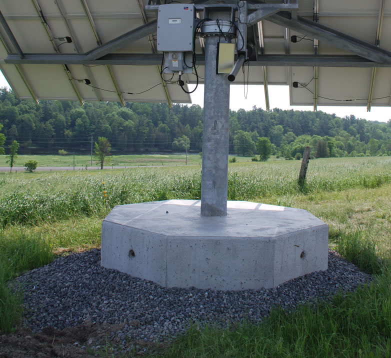
There are two common approaches to anchoring these type of poles. They both involve a large concrete base with an integrated ring of studs cast into the concrete. When the concrete is set, then the base flange of the pole is bolted onto the studs. This requires access to some type of lifting machinery to position the pole.
The two different methods are to excavate a hole in the ground, and fill that hole with concrete. When properly done, the end result has a finished appearance. The other is a variation on the ballasted mount, a similar amount of concrete is used to form a large base of concrete is poured on the ground level. This can be used on sites where excavation is not practical. Both round and square bases are used. In my opinion the round bases are more attractive. It would normally be easier for a DIY enthusiast to construct a rectangular form. Full-time installers may use re-usable forms and it is easier for them to produce a circular base. The proponents of the ballasted approach state that the benefit is a faster installation time. They simply level the site, put in a base of crushed stone and then assemble the form and pour.
![]()
This is an example of a base and in the background the steel forms that were used by the manufacturer to form the base. The octagonal shape with sloped sides is interesting. Note that any form with a sloped side such as this one tends to float up on top of the concrete when it is wet, and so a LOT of downward force is required to keep the form in place until the concrete has cured.
In theory, the base that is poured into a hole excavated would seem to be stronger because the earth surrounding the concrete cylinder would also provide support against sideways and uplift forces. Always consult with a Civil Engineer or Structural Engineer to determine if your soil conditions are suitable for an excavated base, and for the recommended size of the base.